What it is:
This device takes the signal from an RC receiver, the kind you would plug your
servos into in an RC car or airplane. Based on that RC signal it
outputs controlled power to pair of motors up to 18V and 4A. The
control is proportional (variable speed), and goes in both directions without
bias in either direction, making it well suited to tank drive vehicles. The
logic is based on a PIC18F1320. The best part of this project is not just
that it allows you to make a relatively cheap RC dual motor controller, but
that using this code and input scheme you can take any PIC microcontroller
project and add radio control with as many channels as you like using only one
pin to receive it all. Besides using those values to control other robot
functions you can still use any of the ports on your receiver, including the
ones that are going to the control board, to control servos.
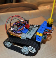
Because it's not that much fun controlling two motors without a robot for them
to drive I have built the system into a Lego robot . This motor controller
could be used for any skid steer robot, or you could simplify it to one motor,
use the other port for a servo and make a vehicle that steers like a car.
If the Lego part of the project is of interest to you the connectors are
explained in step 4 and the lego body is layed out in step 5.
This project requires basic electronic tools and a programmer that can work
with 18F series chips.
The
hardware:
The electronic hardware is fairly simple. The PIC 18F1320 handles all the
signal interpretation, requiring only 2 filtering diodes. The same chip
generates motor control signals for both motors. The other big chip on the
board is a L298n motor driver. This chip contains two H-Bridges capable of
driving a motor with up to 4A of current at up to 18V. Besides the chips the
one other large component is a 5V regulator to give the PIC a good power
supply. Besides those you have a handful of inexpensive diodes and resistors. A
specific parts list is in step 1.
The software:
The software for the chip has a portion that interprets PWM* servo control
signals into a variable, and another portion that generates two motor control
PWM* signals. These parts could each potentially be used to make either a
system that does something else based on radio control commands, or a motor
controller that is driven by other means. The code could easily be expanded to
read many (I'm talking 8 or more) PWM signals. You could take one of those huge
$500 airplane remote control systems and have a chip read every channel! What
you did with all that control data would be up to you.
*As a side note, these are both pulse width modulated (PWM) signals but the
motor control signal pulses on and off to vary the average power to accomplish
various motor speeds, while the servo signal works by sending different widths
of pulse which are read as relative command values.